Major transformer breakdowns, fires, and explosions are rarely instantaneous. Over 95% of severe failures escalate progressively over months or years from latent defects. In their early stages, these incipient faults produce faint anomalies that are imperceptible to the naked eye or human senses—such as localized hot spots, minor oil seepage, latent insulation moisture, bushing tracking, low-frequency vibrations, and trace dissolved gases. Consequently, they are easily overlooked during routine field walkdowns.
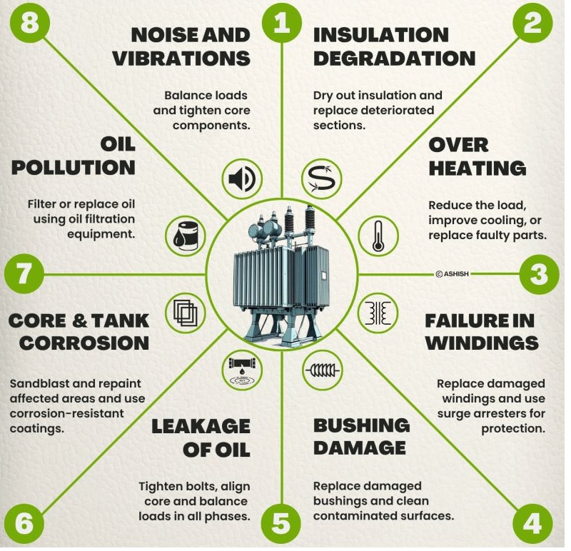
The following sections detail the 8 most common categories of typical transformer defects (Transformer ratings range from 11kV, 33kV, 110kV, 220kV, to 500kV.), compiled as a practical field guide for substation O&M, electrical, and industrial power distribution engineers.
I. Manifestations
Early Stage: Faint increase in oil moisture and dissipation factor (tan δ). Weak partial discharge (PD) blue glow visible via nighttime ultraviolet (UV) imaging. Slight yellowing of the pressboard.
Mid Stage: Continuous decline in oil Breakdown Voltage (BDV). Trace amounts of Hydrogen (H2) and Acetylene (C2H2) detected via Dissolved Gas Analysis (DGA). Winding DC resistance unbalance factor exceeds limits.
Late Stage: Dielectric breakdown during high-potential testing, inter-turn insulation short circuit, or Buchholz relay trip, causing catastrophic winding burnout.
II. Primary Root Causes
Ingress of atmospheric moisture due to gasket failures in the main tank or conservator, or degraded dehydrating breathers; thermal aging of paper insulation from prolonged overloading; copper/carbon particulates forming conductive bridges in the oil; repetitive micro-damage to insulation from lightning and switching surge overvoltages.
III. Corrective Actions
Immediate Response: Perform hot oil circulation under vacuum and double-stage precision oil filtration. Completely replace the oil if moisture or dissipation factor exceeds critical limits.
Overhaul Maintenance: Un-tank the unit for a core-and-coil inspection. Replace aged, carbonized, or damaged winding and lead insulation, followed by re-wrapping and curing.
Limits & Criteria (for ≤35kV Transformers): Oil BDV ≥35kV; moisture content ≤ 35ppm under normal operation; dielectric dissipation factor tan delta ≤2.5% at 90℃.
I. Manifestations
Early Stage: Infrared (IR) thermography reveals a localized temperature delta (△T) of 3–8°C at bushings, radiators, or core clamps. No audible noise or alarms.
Mid Stage: Top oil temperature (TOT) remains chronically elevated. Oil color darkens with accelerated oxidation. DGA indicates rising carbon oxides (CO, CO2) and hydrocarbons. Radiator fouling/clogging occurs.
Late Stage: Winding hot spot temperature exceeds 120°C, causing rapid insulation carbonization and massive gas evolution. Critical tripping of the Buchholz relay (heavy fault) occurs, leading to terminal asset failure.
II. Primary Root Causes
Chronic overloading or severe three-phase load unbalance; cooling fan/oil pump failures or fouled radiator fins; high-resistance loose connections at terminal lugs or tap changer contacts; core multi-point grounding inducing massive eddy current overheating; poor substation ventilation or intense solar radiation blocking heat dissipation.
III. Corrective Actions
Live/Field Remedies: Rebalance the three-phase load; clean external fouling from radiator fins; repair/replace failed cooling fans or pumps; optimize room ventilation.
Outage/Overhaul Maintenance: Clean, re-face, and torque down loose terminal connectors and tap changer contacts, replacing oxidized components. Troubleshoot core insulation to eliminate multi-point grounding faults.
Limits & Criteria: Winding temperature rise over ambient ≤65 K, maximum hot spot temperature ≤105℃ TOT under normal operation ≤85℃ (for ONAN/ONAF).
I. Manifestations
Early Stage: Spikes in partial discharge (PD) metrics. Low-level gas generation in oil (primarily hydrocarbons). Faint, progressive increase in winding DC resistance unbalance.
Mid Stage: Frequent Buchholz light gas alarms. Sharp, distinct acoustic anomalies from inside the tank. Output voltage phase shift. Exceeded DC leakage currents. DGA confirms trace Acetylene (C2H2).
Late Stage: Electrical arcing punches through the remaining dielectric barrier. Differential protection and Buchholz heavy-gas protection trip Covertly. This triggers winding melt-down, oil eruption, and catastrophic fire.
II. Primary Root Causes
Degraded inter-turn insulation due to moisture, thermal aging, or metallic particulate contamination; dielectric puncture from lightning or switching surges; physical winding displacement, deformation, or insulation tearing caused by massive electromagnetic forces during external through-fault short circuits.
III. Corrective Actions
Immediate Response: Execute vacuum oil purification to remove moisture and particulate impurities. Check surge arresters. Stop operations for immediate electrical diagnostic tests (DC resistance, turns ratio, SFRA).
Overhaul Maintenance: Un-tank the unit to replace damaged coils. Re-wrap insulation, apply vacuum varnish impregnation, and oven-cure. Replace the entire winding assembly if structural damage is extensive.
I. Manifestations
Early Stage: Surface contamination/pollution buildup on porcelain or composite sheds. Faint blue corona tracking and audible "hissing" during humid or rainy weather. No protection alarms.
Mid Stage: Permanent carbonized tracking paths form on the insulator surface. Bushing test tap (potential tap) grounding current or dissipation factor (tan δ) exceeds limits. Hydrogen (H2) levels rise.
Late Stage: Internal catastrophic breakdown of the condenser core or shattering of the porcelain insulator, leading to a major phase-to-ground or phase-to-phase fault, triggering oil eruption or flashover tripping.
II. Primary Root Causes
Deposition of salt spray, industrial dust, or chemical pollutants forming a conductive layer when damp; structural micro-cracks from improper rigging during installation or cyclic thermal stress; top seal breakdown allowing water ingress; poor grounding or open-circuit of the bushing test tap, creating a floating potential discharge.
III. Corrective Actions
Field Remedies: Schedule a brief outage to clean insulator sheds and apply Room Temperature Vulcanized (RTV) silicone anti-pollution coatings.
Outage Maintenance: Inspect, clean, and securely ground the test tap. Replace bushings displaying structural cracks, deep carbon tracking, internal moisture ingress, or degraded sealing gaskets.
I. Manifestations
Early Stage: Faint weeping/sweating of oil at flanges, weld seams, or the main tank base. The oil sheen returns after being wiped clean. No active dripping; highly prone to being ignored.
Mid Stage: Continuous active dripping. Pronounced oil pooling on the pad or tank surface. Accelerating loss of oil volume. As the transformer breathes, ambient moisture is drawn back through these leak paths.
Late Stage: Massive oil loss from ruptured welds or total gasket failure. The oil level falls below the critical threshold, exposing the active core and windings to the gas headspace, triggering immediate flashover or fire.
II. Primary Root Causes
Nitrile/rubber gaskets suffer thermal embrittlement, compression set, or chemical aging; uneven torque application on flange bolts or displaced gaskets during assembly; pinholes or corrosion-through on pipe walls and weld seams due to standing water; localized structural stress cracks from chronic vibration.
III. Corrective Actions
Minor/Scheduled Maintenance: Replace degraded gaskets and retorque flange fasteners using cross-pattern method to standard specifications. Deploy specialized polymer sealants or online composite wrap technologies for minor crack encapsulation. Replace weeping valves.
Overhaul Maintenance: Drain oil below the fault line, thoroughly degrease the area, and re-weld corroded seams. Execute comprehensive rust conversion and apply high-durability protective coatings.
I. Manifestations
Early Stage: Oil appears visually clear. Laboratory analysis reveals minor upticks in moisture and particulate counts; dissipation factor exhibits a slight upward trend.
Mid Stage: Oil color darkens significantly; sludge and particulate deposits accumulate at the bottom of the tank. Breakdown voltage (BDV) decays. DGA indicates rising combustible fault gases (H2, CH4, C2H4).
Late Stage: Extreme oil acidification and high levels of suspended carbon particles. BDV collapses below 20 kV. DGA indicates critical Acetylene concentrations. Internal flashover becomes imminent.
II. Primary Root Causes
Defective tank sealing or failed breathers letting in moisture and particulate matter; continuous high-temperature operations accelerating oil oxidation, yielding acidity and insoluble sludge; internal localized PD or thermal hot spots cracking oil hydrocarbons into combustible gases.
III. Corrective Actions
Mild Contamination: Line up a dual-stage vacuum oil purifier for online or offline conditioning to degas, dehydrate, and filter out particulates. Introduce full oil reclamation (adsorbent earth processing) if acid neutralization is required.
Severe Degradation: Drain and discard the condemned oil charge. Flush the internal core-and-coil assembly to remove stuck sludge. Vacuum-dry the insulation matrix and fill with new, certified mineral insulating oil.
Limits & Criteria (In-Service Limits): Total Acid Number (TAN) ≤ 0.1mg KOH/g; flash point decrease ≤5℃ from baseline; zero visible free carbon.
I. Manifestations
Early Stage: Faint increase in no-load losses. Faint fluctuations in the core-to-ground earth leakage current. No external anomalies.
Mid Stage: Formation of a closed loop across the core laminations due to multiple ground points, driving massive circulating currents. Core grounding current surges well past the industry benchmark of 0.1A. Localized core overheating thermally cracks the surrounding oil.
Late Stage: Inter-laminating insulation burns out, causing large-scale core melting and welding. No-load losses skyrocket, and the localized thermal energy triggers a secondary catastrophic winding fault.
II. Primary Root Causes
Condensation and free water accumulation due to long-term sealing degradation, causing internal corrosion; foreign metallic debris (e.g., loose washers, weld slag, or wire clippings) left behind during historical work; damage to core-clamp insulation or structural shifts under short-circuit forces creating an unintended second ground path.
III. Corrective Actions
Outage/Overhaul Maintenance: If a multi-point ground is verified, attempt to clear temporary or "soft" shorts using the capacitor discharge method or controlled current burn-off. If unsuccessful, un-tank the core to manually clear the bridge, repair the insulation, and retest to verify that exactly one intentional, solid ground point exists.
I. Manifestations
Early Stage: Faint amplification of the normal 100 Hz / 120 Hz electromagnetic humming sound. Faint tank resonance matching load swings.
Mid Stage: Harsh, metallic rattling, buzzing, or clicking noises. Severe high-frequency structural resonance of radiator panels and connected piping. External structural bolts vibrate loose or shear off.
Late Stage: Core lamination stack loosens completely, skewing the magnetic circuit. Continuous heavy mechanical vibration chafes winding insulation, shears internal leads, cracks tank weld seams, and induces systemic oil leaks.
II. Primary Root Causes
Loosening of core tie-rods, through-bolts, or clamp structural members due to prolonged cyclic thermal expansion and operational vibration; severe three-phase load unbalance creating an asymmetrical magnetic flux layout and uneven alternating forces; degraded or missing anti-vibration pad mounts under the transformer base.
III. Corrective Actions
Field Remedies: Manage downstream distribution configurations to minimize phase unbalance; check and tighten all external structural bolts, fitting lock washers. Affix vibration-damping elastomeric pads to resonant radiator braces.
Overhaul Maintenance: Perform an out-of-tank overhaul to torque core tie-rods, flitch plates, and clamping frames down to standard torque ratings. Re-shim or replace damaged winding pressure pads and internal wood/pressboard structural supports.