
Contact resistance refers to the resistance that occurs at the interface between two conductors in contact. From a microscopic perspective, even if the surface of the conductor appears smooth, many tiny asperities can still be observed under a microscope. When two conductors come into contact, the actual contact area is only a small portion of the theoretical area. The current flows through these microscopic contact points, thereby forming contact resistance.
Excessive contact resistance can lead to local heating, increased energy loss, and in severe cases, even result in burning or open-circuit faults. Therefore, regularly measuring the contact resistance of high-voltage switches is an essential means of ensuring the reliable operation of power systems.
For new switchgear, measuring contact resistance mainly verifies whether the product performance meets design requirements and evaluates the quality control level during manufacturing. Theoretically, the contact resistance of new equipment should remain at a low and stable level within the specified tolerance. This is because new contacts are usually smooth and clean, with good electrical conductivity and tight contact pressure. Measuring contact resistance at this stage helps identify potential issues in manufacturing processes or material selection, preventing failures after installation.
When testing new switchgear, it is crucial to ensure a stable test environment, as temperature, humidity, and electromagnetic interference may affect the results. For example, high ambient temperatures can increase metal resistivity, leading to higher measured resistance, while excessive humidity may cause condensation on the contacts, affecting stability. Thus, testing should be conducted under standard environmental conditions — typically 25°C temperature and 40–60% relative humidity.
The test instrument should comply with relevant standards, and its parameters must be properly configured to ensure accuracy.
For aged switchgear, contact resistance measurement primarily aims to detect wear, oxidation, and corrosion that occur during long-term operation. Over years of service, contact surfaces gradually deteriorate, leading to increased resistance. Frequent operations cause friction and pitting on contact surfaces, reducing the effective contact area. Additionally, harsh environments — such as humidity, dust, or corrosive gases — accelerate oxidation and corrosion, further worsening the contact resistance.
Contact resistance measurement must comply with strict international standards to ensure accuracy and consistency.
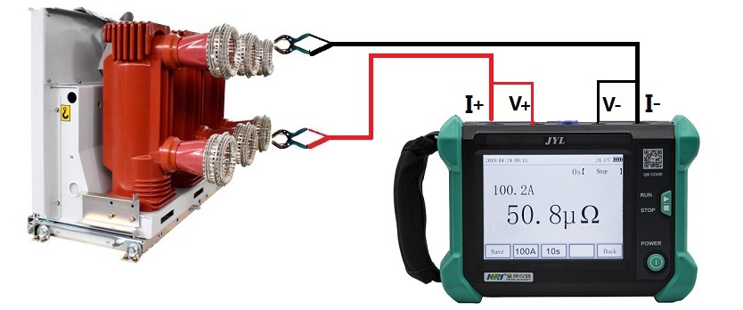
For instance, IEC 60298 specifies that for medium-voltage metal-enclosed switchgear and controlgear, contact resistance between contacts and busbar connections should be measured using a micro-ohmmeter, and the value should not exceed 100 μΩ.
To minimize errors:
Select a high-precision measuring instrument and regularly calibrate it using standard resistors.
Inspect test leads carefully, using short and sufficiently thick cables to reduce lead resistance.
Clean the contact surfaces to remove oxidation, oil, and dirt before testing.
Perform multiple measurements and take the average to minimize random errors.

A newly installed 10 kV vacuum circuit breaker (Model: VS1-12) was tested to verify factory quality and installation compliance.
Objectives: confirm contact material (Cu-Cr alloy), contact pressure, and detect any process defects (e.g., uneven coating) or installation deviations (e.g., misaligned busbar joints).
Procedure: wiped terminal surfaces with anhydrous alcohol to remove dust; oxidation removal was unnecessary due to the new condition of the contacts.
Reference: used manufacturer’s specification (≤50 μΩ) as the benchmark.
Result:
Measured contact resistance was 32 μΩ (standard ≤50 μΩ).
The measurement was stable (deviation ≤3 μΩ), confirming that the breaker met factory quality requirements and was correctly installed — ready for service.
The same substation had a 12-year-old VS1-12 breaker. The purpose was to detect aging and wear, as long-term operation leads to oxidation, pitting, and increased resistance.
Preparation: removed oxidation using fine sandpaper and a metal cleaner, then wiped surfaces with alcohol.
Historical data: 2019 – 42 μΩ; 2021 – 55 μΩ; 2023 – 68 μΩ.
Current test (2025): 75 μΩ (standard ≤50 μΩ).
Analysis:
The resistance increased by 13 μΩ/year from 2019–2023, and 17 μΩ/year from 2023–2025 — showing an accelerating degradation trend.
Inspection revealed loose bolts (torque reduced from 35 N·m to 20 N·m) and terminal corrosion (green copper oxide). Thus, the excessive resistance was caused by a combination of loose connections and corrosion.
Action Taken:
Retightened bolts to 35 N·m, replaced corroded terminals, after which resistance dropped to 45 μΩ.
Updated maintenance plan: shortened the test cycle from once per year to once every 6 months, monitoring resistance trends.
If resistance continues to rise, replacement of contacts or the entire unit should be considered.
Contact resistance measurement is of critical importance for both new and aged switchgear.
For new equipment, it serves as a key tool to verify manufacturing quality and performance before commissioning, helping detect potential defects early.
For aged equipment, it acts as an effective diagnostic method for monitoring equipment health, identifying aging or wear, and preventing unexpected failures.
Through continuous monitoring and analysis of contact resistance trends, maintenance teams can take proactive measures to ensure safe, stable, and reliable operation of power systems.
Other Related Articles:
Why Does the Contact Resistance Testing Need 100A or Higher?
Hazards and Treatment of Excessive Contact Resistance of Circuit Breakers or HV Switches
How to measure the contact resistance without changing the circuit?
How to Correctly Test the Contact Resistance of HV Switchgear or Circuit Breaker?
Why Does Excessive Contact Resistance Occur In Electrical Secondary Circuits?
What is the Testing Checklist for 110kV/220kV Substation Acceptance and Maintenance Testing?
More Transformer Testers from Kingrun


Kingrun Transformer Instrument Co.,Ltd.


