
Leakage current is a parameter that reflects the insulation strength of products in the electrical industry, so what exactly is leakage current? What is the purpose of measuring transformer leakage current?
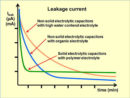
Leakage current refers to the tiny induced current generated around the insulating material under the action of electric field force. The unit is generally expressed in microamps. It is widely found in coil windings, capacitors, cables and other components or conductors through which current flows. The insulating layer, because the insulating layer is non-conductive, but in fact almost no material is absolutely non-conductive, and when a voltage is applied across any insulating material, a certain current will always flow. Then the purpose of measuring the leakage current of the transformer is to prevent its winding from being affected by the environment or used for a long time, resulting in insufficient insulation strength and causing insulation breakdown to burn the transformer.
Reasons for excessive leakage current of transformers:
1 The transformer is usually AC, and the leakage current is too large, which is mostly caused by the parasitic capacitance of the winding. It is not that the insulation resistance is too small, but the distance between the winding and the casing (body) is too close, and the parasitic capacitance is too large, resulting in a large capacitive leakage current. The way to determine whether this is the reason: use a high-precision current mutual inductance Connect a resistance of about 100 ohms to the secondary side of the transformer, and use an oscilloscope to check the voltage on the secondary side of 100 ohms. If the phase of the voltage is more than 60 degrees out of phase with the power supply voltage, it means that there is indeed a large capacitance. Sexual Current Component
2. The problem of the material of the silicon steel sheet itself, some cheap silicon steel sheets often have a large magnetic impedance, resulting in excessive leakage current.
3. The problem of silicon steel sheet installation, because the transformer core is superimposed by a large number of silicon steel sheets, if the superposition is not good and the gap is large, it is easy to generate leakage current. It is recommended to check whether there is a problem with the iron core.
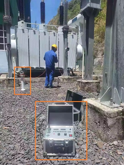
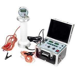
Purpose of Transformer Winding Leakage Current Test
The purpose of transformer winding leakage current test is to check the insulation performance between high voltage to ground, low voltage to ground, and high voltage to low voltage (primary side to secondary side).
The voltage of the DC leakage test is generally higher than the voltage of the megohmmeter and can be adjusted arbitrarily, so it is more effective than the megohmmeter to find defects, and can sensitively reflect the cracks of the porcelain insulation, the internal moisture and local looseness of the sandwich insulation. Deterioration of broken insulating oil, creeping carbonization of insulation, etc.
Notes on transformer winding leakage current test
1. Transformers of 35KV and above (excluding 35/0.4KV distribution transformers) must be carried out to read the leakage current for 1 minute.
2. The pressure part during the test is the same as the insulation resistance measurement. Attention should be paid to the cleaning of the casing surface and the influence of temperature and humidity on the measurement results.
3. When analyzing and judging the measurement results, it is mainly to compare with the same type of transformer and each coil, and there should be no obvious changes.
4. When the microammeter is connected to the high voltage side, the insulating support should be firm and reliable to prevent swaying and tipping.
5. The layout of the test equipment should be compact, the connection wire should be short, and shielded wire should be used, which should be safe and easy to operate; there should be enough distance to the ground, and the ground wire should be firm and reliable.
6. The surface of the test object should be wiped clean and shielded to eliminate the measurement error caused by the dirty surface of the test object.
7. The test object that can be tested in phase should be tested in phase, and the non-test should be short-circuited to ground.
8. The test object with small test capacitance should be added with voltage stabilizer capacitor.
9. After the test is over, the test object should be fully discharged.
10. If the leakage current is too large, you should first check the condition of each equipment in the test circuit and whether the shielding is in good condition. Only after eliminating the external cause can you make a correct conclusion on the tested product.
11. If the leakage current is too small, check whether the wiring is correct and whether there is shunt and disconnection in the protection part of the microammeter.
12. Influence of high voltage connecting wire on ground leakage current:
Since the wire connected to the test object is usually exposed to the air (without shielding), and the pressurized end of the test object is also exposed, the surrounding air may become free, resulting in leakage current to the ground, especially at high altitudes , The place where the air is thin is more likely to be free, and this leakage current to the ground will affect the accuracy of the measurement. Measures such as increasing the diameter of the wire, reducing the tip or adding a halo shield, shortening the wire, and increasing the distance to the ground can reduce the impact on the measurement results.
13. Influence of air humidity on surface leakage current
When the air humidity is high, the surface leakage current is much larger than the volume leakage current, and the surface of the test object is easy to absorb moisture and increase the surface leakage current, so the surface must be cleaned and a shielding electrode should be applied.

The test items are required for 110kV/220kV substation acceptance and maintenance testing(with corresponding tester types):

Kingrun Transformer Instrument Co.,Ltd.


More Transformer Testers from Kingrun


