
In modern power systems, transformers play a pivotal role, with their performance and reliability being crucial for the stable operation of the entire network, to ensure that transformers meet design and operational standards after being installation, repaired and commissioned, Acceptance Testings are an essential step.
This article provides a detailed checklist of the main items involved in transformer acceptance testing after installation, repairing and commissioning, aiming to help readers understand the importance of these tests and their specific implementation methods. By gaining insights into these testing procedures, electrical engineers and technicians can better manage quality control and performance evaluation of transformers, thereby ensuring the safety and efficiency of power equipment. The following sections will delve into the purpose, processes, and technical requirements of each test, offering a comprehensive guide to assist industry professionals in achieving thorough and reliable transformer acceptance.
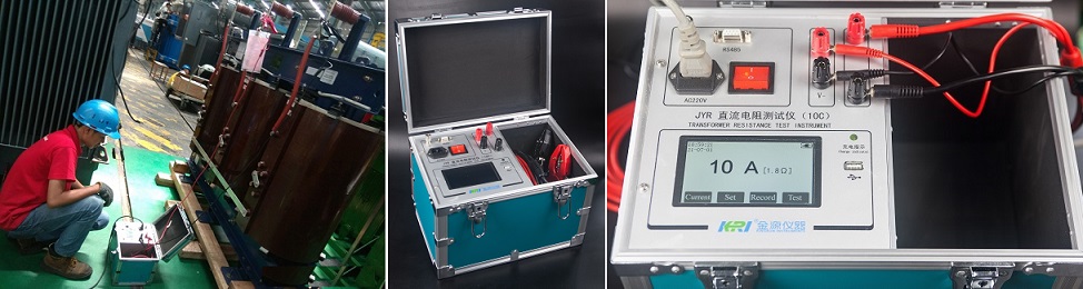
1. Winding DC Resistance Testing:
The principle of this test is to measure the resistance value of the individual windings of the transformer to check the quality and electrical characteristics of the winding connections. Typically, this test involves resistance measurements of each winding of the transformer, such as the high-voltage, medium-voltage, and low-voltage windings.
During the test, the test instrument is connected to each winding of the transformer, and a known current is passed through. According to Ohm's law, the resistance value of each winding can be calculated based on the measured voltage and current values, and by adding the measured By comparing the resistance value with the design value, you can evaluate and identify the quality of the winding connection, poor contact, open circuit, short circuit, etc., and verify whether the transformer winding meets the specification requirements to ensure the stability and reliability of the transformer.
Measure the winding resistance of all winding and all partial connections. The difference between the winding resistance of each phase of the transformer should be less than 2%. That is: [R(max) - R(min)] / R(avr) < 2%. When the low-voltage winding is a delta connection, the DC resistance of each phase should be provided for the semifinished product. The difference between the phases should be less than 2% of the average value. The difference between the DC values obtained from the side of the line should be less than 1% of the average value.
Recommended tester:
JYR9310 (Handheld / Cu&Au /Temp. Convert)
JYR-10C (Economy / Single phase)
JYR-50S (High current / Comprehensive Testing /Three phase)
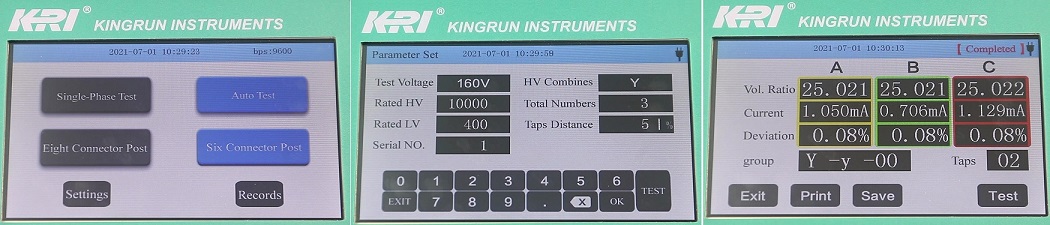
2. Turns Ratio Testing(TTR)
The turns ratio refers to the ratio between the input voltage and the output voltage of a transformer. The purpose of this test is to ensure that the output voltage of the transformer matches the design requirements after maintenance and commissioning, and to verify that its turns ratio meets the specification requirements.
The principle of the turns ratio test is to apply the rated voltage to one side of the transformer while measuring the voltage on the other side. By comparing the measured output voltage with the input voltage, the turns ratio can be determined. Typically, the turns ratio test is conducted under different load conditions to ensure the stability of the turns ratio under varying loads.
Transformer turns ratio testing should be made at all coils and all tap positions. The turns ratio vol deviation of the transformer does not exceed ±0.5% at all tap positions. The connection group is correct.
Recommended tester:
JYT (Handheld)
JYT-A (Leading type)
JYT-B (Angle test / Neutral point / Scott / Z connection)

3. Short-circuit Impedance and Load Loss Testing
The short-circuit impedance test for transformers is primarily used to measure the transformer's short-circuit impedance value. This value is determined by the relationship between the primary side voltage and current when the secondary side is short-circuited and the primary side is supplied with rated current. The short-circuit impedance test helps to understand the inductive and resistive characteristics of the transformer's internal components.
The short-circuit impedance value can verify whether the transformer meets specifications after installation, maintenance, and commissioning. If the short-circuit impedance value significantly deviates from the design value, it may indicate internal issues with the transformer, such as incorrect winding turns or improper winding geometry. Additionally, this test can assess the transformer's iron losses, short-circuit current, voltage regulation performance, and mechanical strength.
The load loss measurement should be made at the rated voltage tap position. The loss measurement is corrected using a correction factor. The correction factor is determined based on the accuracy of the calibrated meter. For measuring load losses with very low power factor (0.03 or less), the phase angle error of all instrument transformers should be corrected. All impedance and load loss values should be converted to the reference temperature (75 °C).
Recommended tester: JYW6300
4. No-load Loss and No-load current testing (including harmonic testing of no-load current)
The no-load test(open-circuit) test of a transformer is a standardized testing method used to assess its performance and quality. During this test, the secondary winding of the transformer remains disconnected from any load, while the primary winding is energized with rated voltage without transmitting power. Various parameters of the transformer are measured during the test, including open-circuit current, no-load losses, voltage regulation performance under load variation, losses in windings and core, as well as insulation characteristics.
The on-load test of a new transformer is a method used to assess its performance and stability under load conditions. The principle of the on-load test involves applying a load to the secondary winding of the transformer and observing and measuring various performance parameters while under load. By monitoring and recording parameters such as output voltage, input current, power factor, and temperature, the on-load test evaluates the transformer's voltage regulation performance under load variations, measures its power losses, and assesses its temperature rise to ensure proper thermal performance.
The testing should be carried out at 50%, 60%, 70%, 80%, 90%, 100%, 105% and 110% of the rated voltage respectively. No-load loss and no-load current measurement.
Measurement of initial no-load loss and no-load current: Before all insulation tests, the no-load loss and no-load current are measured at 10%, 50%, 60%, 70%, 80% of the rated voltage, and then In the range of 90% to 115% of the rated voltage, it is measured step by step with 5% as the primary voltage. The no-load loss and no-load current should be measured on the low-voltage winding. The no-load and no-load current values shall be measured and corrected in accordance with relevant standards.
After all the insulation tests are completed, the loss measurement at the rated voltage will be taken as the actual measured value with the last measured no-load loss value.
Recommended tester: JYW6100
5. The Temperature Rising(Heat run) Testing.
This test is mainly to check the structural performance of the transformer after installation, repairing and commissioning, specifically to check whether the transformer can be cooled quickly, that is, whether the heat generated by the total loss during the operation of the transformer can be quickly dissipated, and whether it meets the requirements of the IEC standard. Temperature rise, as well as the limit value of winding temperature rise, also check whether some other components have local overheating phenomenon, such as iron core, fuel tank and structural parts, etc. Generally, after insulation, loss, voltage ratio and DC resistance tests, according to the nameplate data or relevant regulations.
The principle of the heat-run test is to apply a rated load current to the winding of the transformer, run it continuously for a period of time, and then measure the temperature rise of the winding. Typically, temperature rise tests are conducted under full load conditions of the transformer to simulate operating conditions in actual operating environments.
Recommended tester: JYR-40E
6. Transformer Insulating Oil Testing.
The insulating oil test includes physical, chemical, and electrical performance tests and provides a factory test report. The breakdown voltage strength(BDV) test was carried out with a 2.5 mm ball gap, and the breakdown voltage should not be lower than 50 KV; the breakdown voltage strength test was performed using a plate electrode, and the breakdown voltage should not be lower than 40 kV. Measure the dielectric loss factor of the oil, the dielectric loss factor should be less than 0.5% (at 90 °C), and the moisture content should be less than 15 mg / l. After the transformer oil is injected into the transformer tank, after completing all the specified factory routine test items, the micro-water analysis and chromatographic analysis in the oil shall be carried out. The acetylene content shall be 0, and the analysis results shall be provided to the operating unit. The oil in the on-load tap-changer oil tank should also be subjected to simplified tests and micro-water tests. The oil pressure is greater than 40kV/2.5 mm and the moisture content should be less than 15 mg/l.
Recommended tester:
JY6611 (oil breakdown voltage testing)
GTD-61A (Tan Delta / DDF)
JYC (Dielectric Loss / Tan Delta)
7. Transformer Winding Insulation Resistance Testing
The insulation resistance test for transformers is a method used to assess the integrity and quality of the transformer windings' insulation. In this test, typically, the insulation resistance between the high-voltage winding and the low-voltage winding with respect to the tank is measured, as well as the insulation resistance between the low-voltage winding and the high-voltage winding and the tank.
The principle of this test relies on Ohm's law, which describes the relationship between voltage, resistance, and current. By applying a certain DC voltage and measuring the corresponding current, the insulation resistance between windings and ground can be calculated. The purpose of the insulation resistance test is to detect any leakage current between windings or between windings and ground, and to evaluate the integrity and quality of the insulation.
The insulation resistance test can detect the insulation integrity of transformers after installation, repairing and commissioning, identify any potential leakage issues, and assess insulation quality. Higher resistance values typically indicate good insulation integrity, while lower resistance values may suggest potential insulation problems.
Recommended tester:JYM
8. AC Hipot testing
The AC Hipot test of windings along with bushings is one of the most effective methods to evaluate the insulation strength of transformers. The principle of the test involves applying a high voltage, higher than the rated voltage but for a very short duration, to one end of the transformer while grounding the other end. If the insulation does not break down or exhibit surface flashover, it indicates that the insulation strength can withstand the applied high voltage, thus passing the Hipot test.
The AC Hipot test can detect major insulation defects such as moisture ingress and concentrated defects, including main insulation cracking, winding displacement, insufficient clearance of lead insulation, and contamination by water and dirt on the insulation. Additionally, it can identify local insulation defects through the relationship between current and leakage current.
Compared to AC voltage, DC voltage tests are more effective in identifying end insulation defects, as the voltage is divided by the insulation resistance under DC conditions. However, AC Hipot testing may exacerbate some existing weak points in the insulation. Therefore, prior to performing the AC Hipot test, it is essential to conduct preliminary tests on the transformer, including insulation resistance, polarization index, leakage current, and dielectric loss measurements. Only if these preliminary test results are satisfactory should the AC Hipot test be conducted. Otherwise, necessary corrective actions should be taken, and once all parameters meet the required standards, the AC Hipot test can be performed to prevent unnecessary insulation damage.
The test voltage for ACHipot testing is usually generated using a high-voltage test transformer. For transformers with large capacitance, a series resonance circuit can also be used to generate the high voltage.
Recommended tester: JYDHV
Related Articles:
What are the Acceptance Testing Items for Transformer Installation, Commissioning and Repair?
What tests Must be done(FAT) before a transformer leaves the factory?
What is the difference between transformer "Type testing"and "Factory acceptance testing"(FAT)?
What is the "Type Test" of Transformer( with example analysis)?
Kingrun Transformer Instrument Co.,Ltd.


More Transformer Testers from Kingrun


